Pulse Driven Induction Electrostatic Motor
(See this page.)
Principle
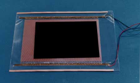
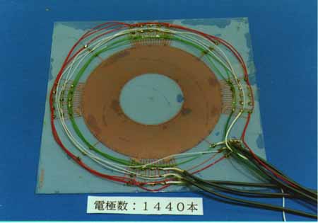
Figure 1 shows a photo of Pulse Driven Induction Electrostatic Motor[1].
This motor consists of two thin films, slider and stator.
Stator film contains 3-phase parallel electrodes, and its surface are covered by isolation layer.
On the other hand, slider has a thin layer that has small conductivity, and does not have any electrodes nor tooth structure.
|
 |
| Figure 1: Pulse Driven Induction Electrostatic Motor |
|
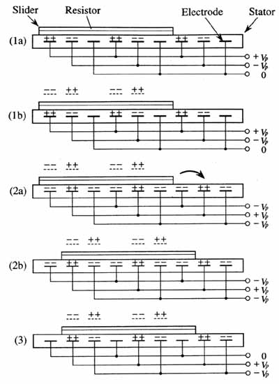
Figure 2 shows the principle of operation.
To operate this motor, place slider film onto stator film, and:
- Induce charges on slider surface,
- Drive slider by chaging the stator voltage, and,
- Recharge on slider surface, and move to the second step.
By repeating this sequence, slider is driven by step motion.
The following is detail descriptions of the sequence.
- (Initial charge step)
At first, slider has no electric charge.
As shown in figure 2 (1a), apply (+,-,0) voltages on three poles of stator electrodes, and induce electric charges on slider surface.
Each electric charge on slider surface have reverse polarity of the voltage of facing stator electrode.
By this operation, the voltage pattern is copied on slider surface as electric charge pattern.
The time constant of this charge operation is determined by both capacitance between stator and slider, and surface resistivity of slider.
For example, the time constance is 1 second, in case of figure 1 motor.
After finishing this charge step (figure 2 (1b)), slider is attracted to stator by electrostatic force, and is held strongly by friction force.
- (Drive step)
As shown in figure 2 (2a), switch stator voltage pattern to (-,+,-).
By this switching, electric charges on stator electrodes can change instantly, but electric charges on slider can not.
As same as the initial charge step, it takes some time for electric charges on slider to reach new equilibrium.
Therefore, right after switching, the charge and voltage distribution shown in figure 2 (2a) appears.
At this time, both slider electric charge and facing stator electric charge have same polarity, and therefore, slider gets repulsive force from stator.
At the same time, slider gets thrust force toward right by electrostatic forces from electric charges on side.
As a result, slider is driven one electrode pitch toward right (figure 2 (2b)).
- (Recharge step)
Some electric charges on slider surface will be lost during drive step.
If we repeat the drive step, thrust force will decrease.
Therefore, we recharge slider electric charge after drive step by using the voltage pattern shown in figure 2 (3).
Since the lost electric charges are relatively small, recharge time is far shorter than initial charge step.
|
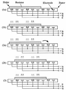 |
| Figure 2: Operation principle |
|
|
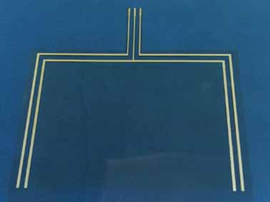
Figure 3 shows one of prototypes whose electrode pitch is 240µm.
The stator film is fabricated using Flexible Printed Circuitry (FPC) board.
The slider film is made of PET whose thickness is 12µm, and is coated by high-resistivity layer, which consists of carbon-black and polyurethane resin.
The surface resistivity of the slider is around 1014[ohm].
Weight of stator and of slider are 0.32g and 0.03g, respectively.
We measured thrust force of this motor by adding some weight to be pulled up by slider, and obtained thrust force of 0.1N.
During measurment, glass beads of 10µm diameter are inserted between stator and slider to reduce fricition force, and gap between stator and slider are filled with dielectric liquid (3M Fluorinert FC-77) to prevent electric breakdown of air gap.
The dielectric breakdown voltage of the stator film was 800V, and breakdown occured in adhesive layer by applying higher voltage.
|
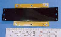 |
| Figure 3: 240µm electrode pitch model |
|
Features
The following lists are some features of this motor.
- Slider does not have tooth structure.
Charge pattern required for operation is copied from stator electrodes by charge process.
This gives us large tolerance for electrodes alignment of stator and for assembling of motor.
However, stable high-resistivity material is required.
- Since electrostatic repulsive force decreases friction between stator and slider while movement, this motor does not require bearings (or linear guides) to keep gap between stator and slider.
Therefore, motor structure can be very simple.
On the other hand, when stopping, the slider is held strongly by electrostatic attractive force.
- Simple structure and ease of assembling allows us to make stacked motors described in the next section.
Stacked motor
Because of its simple structure and ease of assembling, this motor can easily be stacked to get higher power.
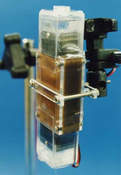
Figure 4 shows an example of stacked motors.
The motor in figure 4 has 40 layers.
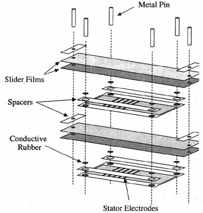
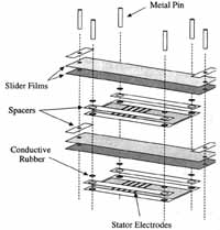
Figure 5 shows the internal structure of the stacked motor.
Stator films and slider films are stacked together with spacer films, and their edges are held by metal pins and acrylic plates.
Interval between each stator film (or each slider film) is 0.35mm.
To utilize both surface of stator films, each layer consists of one stator film and two slider films as shown in the figure.
So, the total number of stator films are 40, whereas the number of sliders are 80.
The metal pins for stator works also as electric feed.
Stator electrodes are connected to those metal pins via washer made of conductive rubber.
Whole motor (figure 4) are held in plastic case and immersed in dielectric liquid.
Both side of slider are connected to output wires, which lead to outside of the case.
Thrust force is transmitted through these wires.
The total weight of the motor, including case and dielectric liquid, is 110g.

| |
Figure 4: Stacked motor
|
|
| |
Figure 5: Structure of the stacked motor
|
|
Results of measurements of thrust force and power are described in the following.
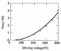
Figure 6 shows a relationship between voltage and thrust force when the motor is driven at 10Hz.
The motor could operate over 100V applied voltage, and its thrust force was proportional to square of applied voltage.
The maximum applicable voltage was limited under 800V due to dielectric breakdown of stator film.
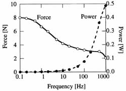
Figure 7 shows characteristics of thrust force and power against operation frequency.
The plot was obtained at 800V applied voltage.
We obtained larger thrust force at lower frequency, and maximum thrust force was 8N.
Power was larger at higher frequency, and maximum power was 0.5W.
| |
Figure 6: Thrust force of the stacked motor
|
|
| |
Figure 7: Power of the stacked motor
|
|
Applications
2-DOF motor[2], Disk type rotary motor[3]
By utilizing various electrodes instead of parallel electrodes, the motor works as a 2-DOF (Degree of Freedom) motor or as a rotary motor.
Figure 8 shows 2-DOF motor.
This motor utilizes matrix type electrodes.
9 electrode elements (3 by 3) makes one set of electrodes.
By expanding the operation principle as shown in figure 2, we can drive slider for any direction on the stator.
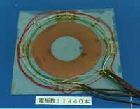
Figure 9 shows disk type rotary motor.
This motor utilizes radial electrodes instead of parallel electrodes.
Figure 9 shows only stator.
We can use any shape of slider.
| |
Figure 8: 2-DOF motor
|
|
| |
Figure 9: Disk type rotary motor
|
|
Transparent motor[4]
ITO (Indium Tin Oxide) is called transparent conductor, and is utilized in, for example, LCD (Liquid Crystal Display) as electrodes.
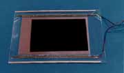
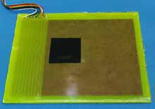
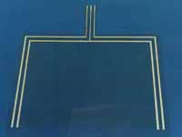
Figure 10 shows transparent electrostatic motor,which utilized ITO electrodes.
Stator is made of PET film of 125 µm thickness and ITO electrodes of 25nm thickness.
The visible electrodes on side are feed line made of silver.
The slider is made of chloroethene to equip transparency.
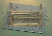
Figure 11 shows cylindrical transparent motor.
In tihs motor, the transparent stator and slider are rapped around transparent acrylic pipe.
| |
Figure 10: Transparent motor
|
|
| |
Figure 11: Cylindrical transparent motor
|
|
Electrostatic paper feeder[5]
Pulse Driven Induction Electrostatic Motor can drive such sliders that have surface resistivity of from 1013 to 1015.
Most papers have such surface resistivity at low humidity (their surface resistivity is sensitive to the humidity).
Therefore, at low humidity, we can directly drive papers as sliders of the motor.
Utilizing this drive, we can realize electrostatic paper feeder, which is more compact than conventional ones.
See also
References
[1]S.Egawa, T.Niino, and T.Higuchi, "Film actuators: Planar Electrostatic Surface-Drive Actuators", Proc. 1991 IEEE Workshop on Micro Electro Mechanical Systems, pp. 9-14 (1991)
[2]T.Higuchi, S.Egawa, T.Niino, and Nishiguchi, "Trial fabrication of Planar 2-DOF electrostatic actuator", JSPE 1992 spring meeting, pp. 329-330 (1992) (in Japanese)
[3]T.Niino, S.Egawa, T.Higuchi, and Nishiguchi, "Trial Fabrication of Disk Type Electrostatic Film Motor", JSME Robotics and Mechatronics Meeting '91, Vol. B, pp. 165-166 (1991) (in Japanese)
[4]S.Konno, Takada, Aida, T.Niino, S.Egawa, and T.Higuchi, "Development of Transparent Film Motor", JSME Robotics and Mechatronics Meeting '91, Vol. A, pp. 73-74 (1991) (in Japanese)
[5]T.Niino, S.Egawa, and T.Higuchi, "Electrostatic Paper Feeder", Journal of JSPE, Vol. 60, No. 12, pp. 1761-1765 (1994) (in Japanese)